Overview
Alt-Rd offers various types of amplifier for infrared detector. The LF-amplifier series is designed for quantum infrared detector (photovoltaic, photoconductive…) and for low frequency analysis. Generic LF-amplifiers are available for standard operations but Alt-RD is specialized in designing custom amplifiers optimized for specific needs. Such applications involve generally the following characteristics:
- very low frequency: Typical frequency range is DC-1kHz. Reducing signal bandwidth decreases the noise rms.
- very small signals: When the noise rms is larger or equal the signal amplitude, specific experimental setup can be used (see below)
- low noise: The LF-series amplifiers uses ultra-low noise electronic components to reduce noise rms value, 1/f noise slope and noise transition frequency.
To achieve good performances, the amplifier must perfectly match the detector. Therefore, a quote request document is provided to let you specify the characteristics of your detector and the desired parameters of the amplifier. Based on these informations, Alt-RD will analyse your request and check whenever it is possible to build your amplifier. If not, changes will be suggested. In some cases, it is possible to design an amplifier for multiple detectors. The quote request allows you to specify such request.
The analysis of small signals is challenging and generic amplifiers may not be adapted. For exemple, small variations of the ambiant temperature can induce signal shifts that can not be handled by the acquisition system. By properly choosing the input coupling or the auto-zero compensation system (see options below), the output signal will remain centered around 0V and signal shifts can be prevented.
To preserve amplifier integrity, many input protections are implemented. The amplifier is protected against reverse or invalid polarities and non-synchronized polarities. Input current limiters preserve internal capacitors from excessive current at start-up. Signal input and output are protected against ESD events and handle continuous short-circuits.
Our amplifiers are generally used for R&D and it is sometimes desirable to change some parameters. Based on your feedback, amplifiers can be updated and modified in some extent. Such updates can be done by Alt-RD but you are allowed to do the change yourself (see option below). In that case, the warranty is voided.
Amplifier options
Our amplifiers can be customized in a large extent to perfectly match your experimental setup. The available options for the LF-series are presented below:
- Detector input coupling: DC or AC (user-specified cut-off frequency, generally between 0.01 and 10 Hz). Generally, small signal analysis requires an AC input coupling.
- 50 Ohm output impedance: By default, LF-series amplifiers exhibits a large output impedance adapted to high impedance acquisition system (106 ohm), to reduce power consumption and preserve battery autonomy. Select this option if you plan to use acquisition system with 50 ohm input. This option increases the power consumption of the amplifier.
- Additional output: A second output with specific gain and input-coupling can be implemented. This option increases the power consumption of the amplifier.
- Digital output (usb): A analog-to-digital (ADC) converter (up to 24bits) can be installed in complement or in replacement of the analog output(s). The benefit is to avoid the use of an external acquisition system. Data are sent to a computer using a USB cable and the UART protocol.
- Auto-zero digital correction system: An AC-input coupling necessarily alter low frequency components of the signal. To prevent this, a digital system can be used instead. A DC signal is internally generated and subtracted to the input signal to ensure it stays center on 0V. This mechanism can be triggered manually or by the falling edge of a trigger signal (the rising edge can be used to triggered a laser).
- Batteries and charger: To reduce power supply noises/perturbations, a set of batteries can be provided, as well as the appropriate charger if needed.
- Replacement component kit: If you plan to tune the amplifier to your application, this component kit consists in a set of resistors and capacitors that could be used to change gains, or cut-off frequencies. The replacement procedure is given as well.
Typical application
This experimental setup [1] is devoted to the estimation of the thermal diffusivity [m²/s] of material, especially those who exhibit low infrared emissivity like metals. It consists in heating the front face of a sample with a laser. Pulses are continuously emitted with a typical frequency of 10 Hz. The pulse duration can be adjusted to increase/decrease the amount of energy absorbed by the sample. An infrared nitrogen-cooled detector is used to monitor the back face temperature. An inverse algorithm is then used to retrieve the thermal diffusivity.
Despite many evolutions of the original flash method by Parker in 1941, the thermal diffusivity estimation of metallic samples is still challenging. Due to a low infrared emissivity, temperature variations (down to 0.001 K) induced by laser pulses are low and infrared radiations emitted by the sample are even lower. It is sometimes possible to avoid the use of a black coating by using the repetitive flash method described here.
Experimental setup containing a low frequency amplifier connected to a N2-cooled infrared detector used to estimate thermal diffusivity of material, especially with low infrared emissivity. 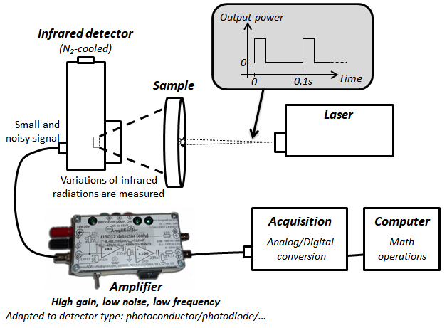
Description of the repetitive flash method [1] 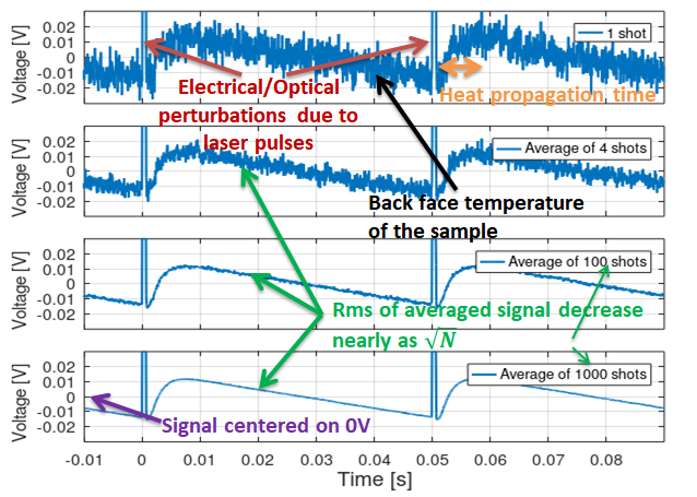
Space-average temperature variations of the sample back face. The effect of averaging the signal over multiple laser pulses/shots is exhibited. The signal noise, mainly due to infrared detector, decreases with the number of averages.
[1] Ruffio E., Pradere C., Sommier A., Batsale J-C, Kusiak A., Battaglia J-L, Signal noise ratio improvement technique for bulk thermal diffusivity measurement, International Journal of Thermal Sciences, Volume 129, 2018, Pages 385-395, ISSN 1290-0729, https://doi.org/10.1016/j.ijthermalsci.2018.03.011, ⟨hal-02369477⟩